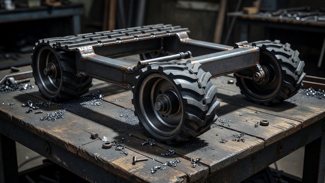
The tread base is the foundation the entire B9 robot rests on, and it is the last major undocumented build section for replica builders working section by section. Every other assembly — legs, torso, collar, head — either bolts directly to it or transmits its weight down through it. Get the tread base wrong, in either dimension or load capacity, and the error compounds all the way up the build. This guide covers frame construction, wheel and tread sourcing, and the structural decisions that separate a display-only base from one that can support a walk-in operator.
Why the Tread Base Comes First
Unlike the collar or radar section, the tread base is not a cosmetic assembly. It is a structural chassis first and a prop second. On the original 1965 prop, the tread section was the widest part of the robot and carried the entire suit — a real actor stood inside it for walk-in shots. Replica builders inherit the same engineering problem: whatever goes on top has to be supported, balanced, and (for walk-in builds) mobile.
Two build paths diverge at this stage, and the decision has to be made before cutting any material:
- Display build — the tread base only needs to support the static weight of the legs, torso, and head above it. Foam, thinner-gauge aluminum, and lighter fabrication methods are viable.
- Walk-in build — the tread base has to support an operator’s weight, provide a stable stance, and often incorporate real or simulated mobility. This calls for a welded steel or heavy aluminum frame, load-rated casters, and a wider safety margin on every joint.
Deciding this now prevents rebuilding the frame later, since the leg section’s attachment points and the torso’s balance point both depend on tread base dimensions established here.
Frame Construction
The builder community has converged on two frame approaches, both documented in existing full-size builds:
Welded steel frame. The more common approach for walk-in and display builds intended to survive repeated convention transport. A rectangular steel tube or angle-iron frame forms the load-bearing skeleton, with the tread’s outer shell built up around it. This is the heavier option but the most forgiving of builder error — steel tolerates a slightly-off weld far better than a bonded joint tolerates a slightly-off bond line.
Aluminum tube and angle iron. A lighter alternative documented in builder reference photos, using 1-inch aluminum tube combined with 1/8-inch angle iron to form the internal support just inside the tread section, giving the rubber tread edges something rigid to key into. This trades some structural margin for a meaningfully lighter finished base — a real consideration for builders who move the robot between a home shop and convention floors without a hoist.
Whichever frame material is chosen, the outer shell — the visible ribbed tread housing — is typically fiberglass or foam panel construction bolted to the frame rather than welded or bonded directly, which lets the cosmetic shell be repaired or replaced without touching the structural frame underneath.
Fastening choice matters more here than on cosmetic sections higher up the build. Bolted joints with lock washers or thread-locking compound hold up far better than pop rivets on any joint that will see repeated transport vibration — a base that gets loaded into a vehicle for every convention appearance works its fasteners loose faster than a stationary display piece. Builders documenting repeated-transport failures consistently point to the same handful of joints: the frame-to-shell mounting points and the caster mounting plate, both of which see the most repeated flex.
Fabrication Sequence and Tools
The tread base is not a section to build freehand from a single reference photo. A workable sequence, drawn from documented full-size builds:
- Establish final dimensions first. Confirm width, depth, and stance height against reference photography before cutting any frame stock — every section built afterward references these numbers, and revising them after the frame is welded means redoing structural work, not just cosmetic work.
- Cut and fit the frame dry before any welding or permanent fastening. Dry-fitting the full frame, checking square and level, catches dimensional errors while they’re still cheap to fix.
- Weld or bolt the frame, then confirm it sits level and square under load before moving to the shell.
- Mount wheels or casters to the completed frame, confirming rated load and lock function before the shell goes on top and hides the mounting hardware.
- Fit the shell panels, budgeting real time for trimming pre-fabricated steel tread-section panels to the frame — this step is routinely underestimated.
- Apply the tread wrap or cast shell surface last, once the frame underneath is fully mechanical-complete and won’t need reopening.
A basic fabrication shop for this section runs a welder (for steel-frame builds) or a strong epoxy/mechanical-fastener system (for aluminum-frame builds), an angle grinder for fit adjustments, and standard fiberglass or urethane-casting tools if the outer shell is molded rather than sheet-fabricated. None of this is specialized equipment beyond what earlier sections of a full build already require — the tread base simply demands more attention to structural tolerance than a cosmetic panel does.
Wheels, Casters, and Mobility
If the base needs to move — even just to be repositioned around a garage, let alone driven at a convention — wheel selection is the single most consequential sourcing decision in this section.
Documented builds in the B9 Robot Builders Club community use CNC-machined solid aluminum wheels paired with genuine rubber tread material, rather than off-the-shelf casters hidden under a cosmetic tread wrap. That combination holds up under repeated loading and looks correct in close-up photography, which matters at conventions where visitors get inches from the prop. Builders who don’t have access to a CNC-machined wheel set generally substitute heavy-duty locking casters rated well above the base’s actual working load, mounted inboard where the tread shell hides them from view.
A few sourcing notes worth confirming before ordering:
- Rated load, not just wheel diameter. A caster rated for the base’s static weight alone will fail under the dynamic loading of being wheeled across an uneven convention-hall floor. Rate for at least 1.5x the expected static load.
- Locking hardware on any caster used for a display stand — an unlocked base rolling during a bump at a crowded show is a real liability, not just a cosmetic problem.
- Tread material sourcing has historically come from small-batch suppliers within the builder community rather than big-box retailers, since automotive or industrial tread stock rarely matches the B9’s tread profile without modification.
Shell Assembly and Tread Fitting
With the frame welded or bolted and wheels mounted, the outer shell goes on next. Documented builder guides describe steel tread-section base units that arrive with plastic side panels requiring trimming and fitting before the outer tread wrap goes on — a detail worth planning for if sourcing a pre-fabricated steel tread unit rather than building the frame from raw stock. Budget time for this fitting step; it is routinely underestimated because it looks like a bolt-on operation until the panels are actually offered up to the frame.
For the tread wrap itself, two approaches are documented among full-size builds:
- Fiberglass or cast urethane shell over the steel or aluminum frame, following the same Smooth-Cast 65D or Task 3 material approach used elsewhere in the build for impact-resistant rigid sections, with the ribbed tread detail either molded in or applied as a separate cast strip.
- Direct rubber tread application, where genuine rubber tread stock is fitted and fastened directly over the frame’s tread profile — closer to the original prop’s construction but more dependent on sourcing tread material that matches the correct rib spacing.
Whichever method is chosen, this is the point in the build where the base’s final width and stance get locked in — every section built afterward (legs, torso) references these dimensions, so confirm final measurements before moving on to the leg section.
Weight and Balance Planning
Once the frame, wheels, and shell are assembled, do a weight check before attaching the leg section. A tread base that is front-heavy, back-heavy, or unevenly loaded side to side will telegraph that imbalance all the way to the top of the finished robot, where it’s much harder to correct. For walk-in builds specifically, confirm the internal frame provides a stable, centered stance for an operator before finalizing any panel that would need to be cut open again to make adjustments.
Frequently Asked Questions
What frame material is best for a full-size B9 tread base?
Welded steel is the more forgiving choice for walk-in builds and repeated convention transport, tolerating minor fabrication error well. Aluminum tube with angle-iron bracing is a lighter alternative documented in builder reference photos, trading some structural margin for reduced overall weight — a real factor for builders without a hoist.
Do I need CNC-machined wheels, or will standard casters work?
Standard heavy-duty locking casters work for most builds if rated for at least 1.5x the base’s static load and mounted where the tread shell conceals them. CNC-machined aluminum wheels paired with genuine rubber tread, as used in documented community builds, hold up better under repeated loading and read correctly in close-up convention photography.
How much weight does the tread base need to support?
For display builds, only the static weight of everything mounted above it. For walk-in builds, the tread base must also support an operator’s full body weight plus dynamic loading from movement — rate every structural joint and caster well above the calculated static load, not at it.
Where do builders typically source B9-correct tread material?
Builder-community sourcing has historically run through small-batch suppliers connected to the B9 Robot Builders Club rather than automotive or industrial retailers, since off-the-shelf tread rarely matches the correct rib spacing without modification. The Replica Prop Forum is the best place to check current sourcing threads before ordering, since supplier availability shifts over time.
Related Reading
The tread base establishes the dimensions and attachment points for the leg section built directly on top of it, and fits into the overall sequence covered in the B9 robot construction overview.