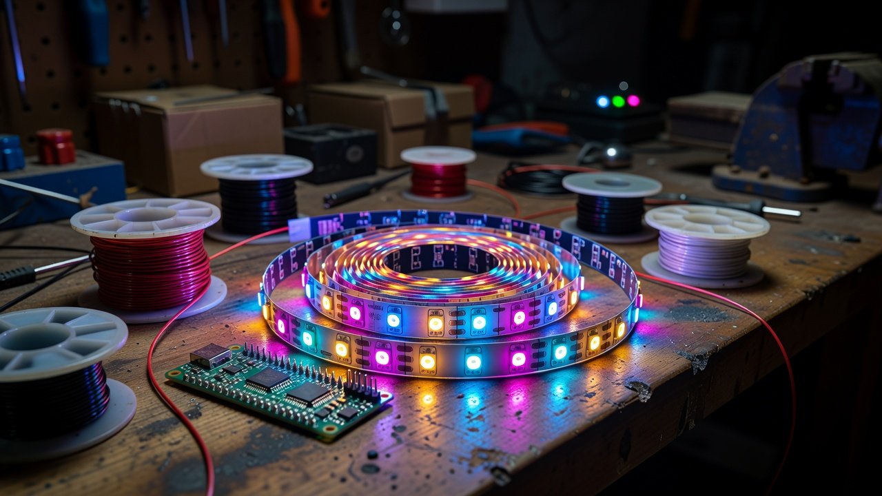
A finished build lit with fixed incandescent or single-colour LED circuits can usually be converted to addressable lighting without tearing the whole thing apart — but only if you plan the power side first. The data side of WS2812 work is easy. The power side is what makes retrofits fail, because the existing wiring in an older build was sized for a load an order of magnitude smaller.
Start with the current budget, not the effects
Each WS2812 draws roughly 60 mA at full white — all three channels at maximum. Mixed-colour animation averages closer to 20 mA per LED in practice.
Do both calculations, because they answer different questions. The average tells you what your supply will actually deliver during normal running. The full-white figure tells you what happens at power-on, during a white flash effect, or when the controller resets and the library defaults to something bright.
A 120-LED retrofit is 2.4 A average and 7.2 A worst case. Existing wiring run for a few incandescent lamps will not carry 7 A, and the existing supply almost certainly will not either. Size for the worst case or clamp the worst case in software with a global brightness limit — and if you rely on software, understand that it does not protect you during the moments before your code runs.
Power injection is not optional at this scale
Feeding a long run from one end drops voltage along the strip. The visible result is colour shift toward red at the far end, because the blue and green dies need more forward voltage than red.
The working rule: inject power at both ends from roughly 1–2 metres onward, and every metre on dense strips. Injection means running a separate pair of adequately-sized power conductors from the supply to that point on the strip — not daisy-chaining through the strip’s own copper, which is the thing you are trying to relieve.
In a retrofit, this is where the existing harness earns its keep. Old lamp wiring is frequently heavier gauge than LED strip needs and already routed to exactly the places that need power. Reuse those runs as injection feeds and pull only thin signal wire for data.
Put a 1000 µF capacitor across 5 V and ground at the strip to absorb the inrush at power-on, and a 300–500 Ω resistor in series with the data line at the first pixel. Both are cheap insurance against the failure that kills the first LED in a chain.
The 3.3 V data problem
This one catches people who have only ever driven NeoPixels from a 5 V Arduino. The WS2812 datasheet requires a logic high of at least 0.7 × Vcc, which at 5 V means 3.5 V minimum on the data line. An ESP32, ESP8266, Pi Pico or Raspberry Pi outputs 3.3 V — below spec.
It sometimes works anyway. “Sometimes” means it works on your bench and fails in the display case in July, which is the worst possible failure mode for a finished build.
Three proper fixes:
- A 74AHCT125 buffer. The standard answer. HCT logic thresholds accept 3.3 V input and output a clean 5 V level. Cheap, fast enough, one chip.
- A dedicated level-shifter board — the BSS138-based four-channel converters and similar modules sold for exactly this.
- Sacrifice the first pixel. Power the first LED from a slightly lower supply voltage (via a diode drop) so its threshold falls within reach of 3.3 V, and let its regenerated 5 V output drive the rest. Legitimate, widely used, and it costs you one pixel.
Tie all grounds together — controller, supply, strip. A floating ground between the controller and the strip produces exactly the intermittent glitching that gets blamed on “bad strip.”
Retrofit routing that avoids disassembly
Addressable strips need three conductors instead of two per circuit, but one chain replaces many circuits — that arithmetic usually works in your favour.
Chain in physical order, not logical order. Sorting out which pixel is which is a software problem; re-running wire inside a finished shell is not. Map the chain afterwards with a simple test sketch that lights one pixel at a time and write the index numbers down.
Leave a service loop at every junction. Retrofit LED work is always revisited.
Use connectors, not solder joints, anywhere you may need to separate a section. JST-SM three-pin connectors are the hobby standard and worth the small voltage drop for the ability to remove a section without a soldering iron inside the build.
Controller choice
Any of the common boards will drive the LEDs. What decides it is how you want to change effects later. An ESP32 running WLED gives you a phone-accessible interface and no code changes for routine adjustments — for a display piece that other people will see and ask about, that is usually the right answer. A small microcontroller running FastLED or the Adafruit library gives you exact control of custom sequences, which matters if you want lighting synchronised to sound or motion.
Either way, set a conservative global brightness in the startup code and make the maximum a deliberate decision rather than a default. That single line is what keeps your power budget honest and keeps the worst-case current from arriving unannounced.
Test order that saves rework
Bench the full chain outside the build, at the length and brightness you intend to run. Measure actual current with a meter — not the calculated number. Then install, with the injection feeds in place from the start. Then write effects.
Builders who reverse the last two steps end up diagnosing voltage-drop colour shift as a software bug, which is a long evening.