The tread base is the foundation of any full-size B9 build, and nothing derails a project faster than getting the wheel geometry wrong. Choose casters that are too small and the robot rocks over every seam in the floor. Mount the drive wheels without accounting for floor clearance and the tread shell drags on indoor tile. This guide works through the wheel and caster selection process the way experienced builders approach it: spec first, then source, then fit.
Understanding the Tread Base Structure
The B9 robot’s lower section is a wheeled platform concealed inside a skirt of decorative tread panels. From a mechanical standpoint, it is a driven cart — typically using a pair of independently powered drive wheels positioned near the center of gravity, with unpowered casters fore and aft providing stability.
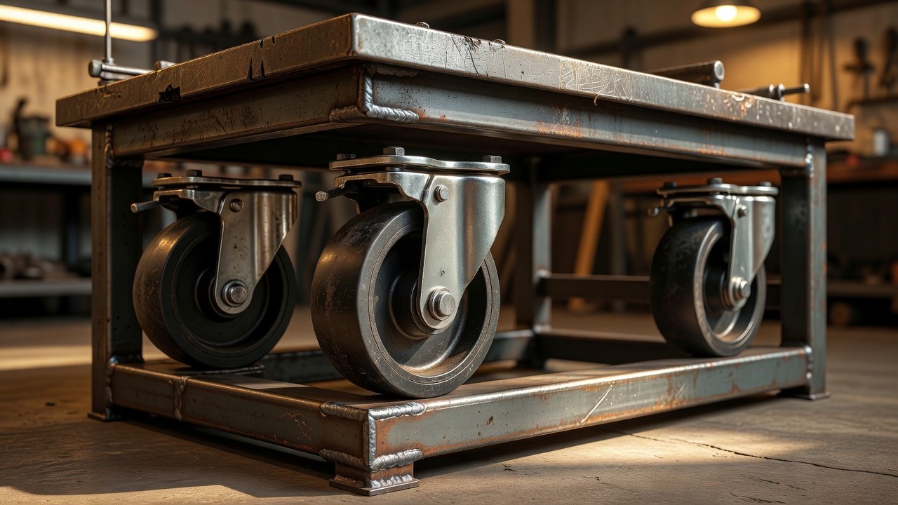
The steel tread frame that surrounds this drive system is typically fabricated from laser-cut mild steel, and several builders in the community have offered welded versions over the years. When you are sourcing the tread sections before you have a complete frame in hand, the key dimension to lock down is the interior floor clearance from the bottom of the frame to the finished floor. Most full-scale builds run in the range of two to four inches of total working height under the skirt. That clearance determines your maximum caster height before you are fighting the shell geometry to get the drive wheels to touch the floor.
Drive Wheel and Motor Pairing
The most common approach for a motorized B9 uses a salvaged electric wheelchair drive system. A two-motor differential drive with one motor per rear drive wheel gives you forward, reverse, and turning without complex mechanical linkage. The motors from mid-weight electric wheelchair platforms (the kind designed for 250–300 lb users) produce enough torque to move a 150–200 lb finished robot on hard flooring without straining.
When selecting or matching drive wheels to a wheelchair motor donor, check three things: the shaft bore diameter, the keying arrangement, and the wheel diameter. Wheelchair drive wheels tend to run 10 to 12 inches in diameter and are hub-mounted. Many builders source new urethane-coated or solid rubber wheels in the 8–10 inch range to keep the overall drive unit low-profile inside the tread base. The wheel must clear the bottom edge of the steel tread frame by at least a quarter inch on all sides to avoid metal-to-metal contact during slight flexing on uneven floors.
Caster Selection: What to Look For
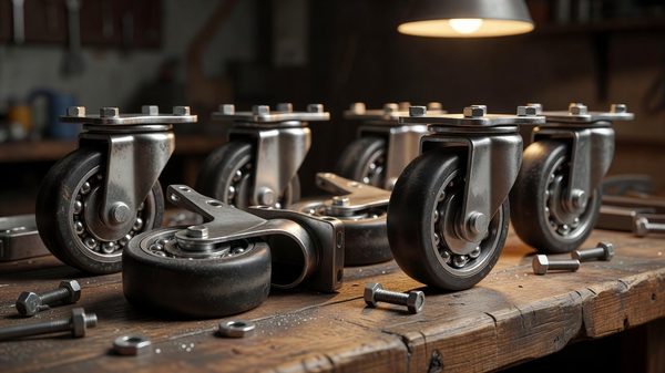
The front and rear casters carry a significant share of the robot’s weight and handle virtually all directional change — the differential drive steers by varying motor speed, but the casters absorb the lateral forces that result. For a full-scale build, you need rigid-stem or plate-mount swivel casters rated well above the calculated load they will carry.
Start with total robot weight plus a safety margin of at least 50 percent. If the finished robot will weigh 160 lbs and you plan four casters, each caster must be rated for at minimum 60 lbs — and that is before accounting for dynamic loading from acceleration, bumps, or ramps. Many builders end up specifying casters rated at 100–150 lbs each even on lighter builds, simply because the rating headroom buys you durability and smoother rolling.
For wheel material on convention or indoor use, polyurethane tread casters outperform steel and hard rubber on most indoor surfaces. They roll quietly, leave no marks, and absorb minor surface imperfections without transferring vibration up through the frame. The tread width matters too: a wider tread spreads load and reduces the chance of sinking into any soft flooring or matting commonly found at convention venues.
Swivel radius is a less obvious spec that catches builders off-guard. A large swivel radius means the caster takes more horizontal space to pivot — fine for open warehouse floors, but potentially a problem inside a tight tread base where the caster might contact the frame during sharp turns. Look for compact-head swivel casters with a short stem and a tight swivel offset.
Fitting and Mounting Height
Getting the caster mounting height right is the step that separates a robot that rolls smoothly from one that requires a builder walking behind it holding the skirt up. The goal is to have the robot sitting level when the drive wheels are fully in contact with the floor and the casters are carrying their share of the weight — not tipping backward onto the rear casters with the front ones floating, and not balanced so far forward that the rear casters lift on acceleration.
Work out the geometry before welding or bolting anything. Set the steel tread base frame on a flat surface, place the drive wheels in position, and use scrap blocks to simulate the caster mounting height. Check levelness with a straightedge across the top of the frame. Then add the actual casters, load the frame to something approximating the upper body weight (sandbags work well for this), and recheck. The loaded height with drive wheels on the floor and casters touching is your true operational geometry.
Stem-mount casters in a round socket give you the ability to fine-tune height by shimming the socket depth before final welding. Plate-mount casters are easier to source in heavier duty ratings but require accurate mounting plate placement to adjust height. Either approach works; the important thing is to leave adjustment capability in the design until you have run the drive system loaded on your actual floor surface.
Tread and Wheel Sourcing Channels
Builders have sourced suitable casters through industrial supply channels — the major names like Grainger, McMaster-Carr, and Uline all carry plate and stem casters in the specifications described above. Local industrial surplus yards occasionally surface heavy-duty casters at significant discounts, which matters when you are buying six to eight units.
For the decorative tread wheels visible on the outside of the B9 tread section — the 32-wheel array in four sizes around the tread panels — these serve no structural purpose and are separate from the drive and caster hardware. They are cosmetic details fitted to the outer skin of the tread section, and their sourcing and fitting involve different considerations from the functional wheel assembly covered here.
The B9 Robot Builders Club remains the primary community reference for builder scrapbooks documenting specific hardware used in completed builds. Reviewing build logs there will show you exactly what other builders have bolted in, including supplier names and part numbers that have worked in practice.
Before You Weld, Roll It
Even experienced fabricators skip the loaded-roll test before final welding of the caster mounts, and it costs them. Set the entire tread base up with all wheels and casters in place, add representative ballast for the upper body weight, and push it across the same type of flooring you expect to use. Listen for scraping, watch for any tendency to pull left or right, and check whether the casters swivel freely through a full 360 degrees without contacting the frame. Make any geometry corrections now. Once the caster plates are welded and the drive system is installed, fixing a misaligned mount means grinding out welds — a job no one wants.
The tread base takes more engineering thought than any other part of the B9 build. Get the wheel geometry right at the start, and the rest of the mechanical work falls into place around a platform you can actually trust to move the robot where you want it to go.